Simulator virtual parts
Here you will find an overview of the components in the simulator panel, their connection and how they are used in the blocks. If you're starting out, go through the first program first. For all subsequent attempts, select Simulator in Device → Processor.
Quick overview of the pins
The connection is ready in the simulator. The pin number in the program must match the component label; by changing the number in the block, you will not connect the component.
Click on the component name to jump to its control and usage procedure.
| Component | Connection | Where to look for blocks |
|---|---|---|
| LED | GPIO 1 to 8, each LED has its own pin | Outputs |
| Button | GPIO 16 and 17 | Inputs |
| Analog Sliders | GPIO 10, 11, 12 | Inputs |
| Joystick | X axis 13, Y axis 14, press 15 | Sensors |
| Rotary encoder | A 18, B 19, press 20 | Sensors; press read through Inputs |
| DHT22 | GPIO 9 | Sensors |
| OLED 128×64 | SDA 21, SCL 22, I2C address 0x3C | Display |
| Servo 180° | GPIO 23 | Motors |
| Servo 360° | GPIO 24 | Motors |
| DC engines | GPIO pair 25 / 26 and 27 / 28 | Motors |
| NeoPixel, 8 LED | GPIO 29 | NeoPixel |
Initialization belongs to the beginning
For joystick, encoder, DHT, OLED, servos, motors and NeoPixel, use the appropriate initialization block. Put it in the initial part of the program after code that runs once and then use the read or control blocks. When looping, don't re-insert the initialization on each pass through the loop.
What do you want to try?
| Attempt | Finished project in ESP IDE |
|---|---|
| One LED turns on and off periodically | LED Flashing |
| Light an LED while a button is held | LED and button |
| The slider changes the numbers in the terminal | Analog Input |
| The terminal shows joystick, encoder, temperature and humidity | Inputs and Sensors |
| The display will show the text and the actuators will be set to the entered values | Display and Drives |
Links load the block project and select the Simulator processor. Save your work in progress before opening it. After loading, wait for the ready simulator and click on Run code; just opening the link does not start the program.
LED: on, off, change brightness
Eight LEDs correspond to pins 1 to 8. With the set digital output block from the Outputs category, set the selected pin to 1 to turn it on or to 0 to turn it off.
Brightness also responds to PWM output. If you want continuous dimming instead of flashing, use a PWM block in the same category and change its rotation on the pin of the selected LED. Do not unnecessarily combine digital writing and PWM on one pin in the same attempt.
Try different brightness levels
- After code that runs once, insert a PWM block from the Outputs category.
- Set pin 1, frequency 1000 Hz and frequency 32768. This PWM block uses a frequency range of 0-65535.
- Run the program. GPIO 1 LED will be dimmed than at full power.
- Change the shift to 65535 and run the program again: the LED will be fully lit. A value of 0 turns it off.
When changing the brightness during the run, use the block for setting the PWM cycle with the same output designation. The frequency determines the repetition of the pulses; for this experiment, leave it at 1000 Hz and only change the frequency.
Click on the colored LED to open its color selection. This changes the color of the display in the panel; both the power-on command and the pin number remain the same. NeoPixel is used to set different RGB colors directly from the program.
Try GPIO 1 LED blinking. Block details: digital output.
Buttons: press is zero
For GPIO Button 16 and GPIO Button 17 hold the button Press with mouse or touch. When released, the input returns to the idle state.
| Status | Digital input value |
|---|---|
| Released button | 1 |
| Button held | 0 |
In category Inputs, use block logic state of a digital pin with number 16 or 17. If you want to recognize a press, compare the result with 0. In the same way, you can read a joystick press on GPIO 15 and an encoder press on GPIO 20.
You can find the finished procedure at LED controlled by a button. Block Details: digital input.
Analog inputs: three sliders
Sliders ADC GPIO 10, 11 and 12 represent adjustable analog inputs. Under each you see the value 0 to 65535. When you first create a panel, they start roughly in the middle, at 32768.
In the Inputs category, use the analog input block and enter the appropriate pin. In its roller you select the output value range: 0–100, 0–255, 0–1023 or 0–65535. You don't change the range of the slider itself; the block recalculates its value to the selected range.
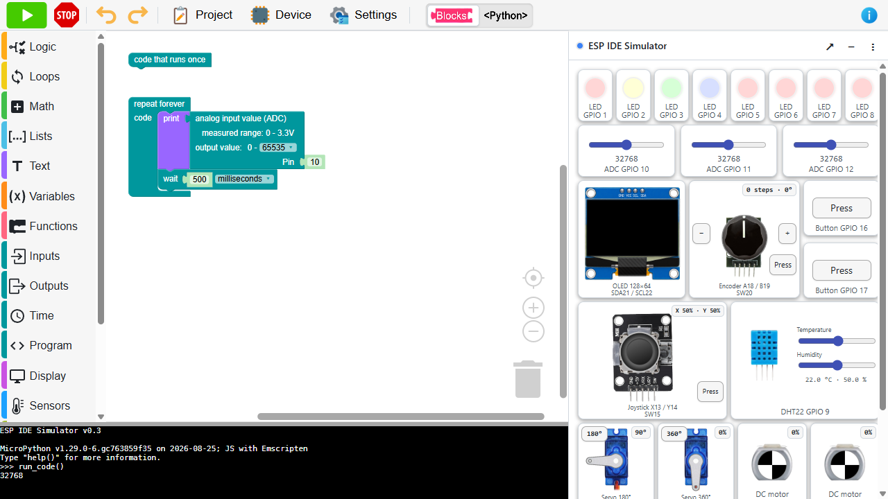
Try reading to the terminal
- Insert the print block from the Text category into repeat forever.
- Instead of text, connect an analog input block with pin 10 and range 0–65535.
- For the dump, insert a wait of 500 milliseconds.
- Run the program and shift ADC GPIO 10. The numbers in the terminal will change based on its location.
Open analog input example in ESP IDE. The link loads the blocks as well as the Simulator processor; save your own project in progress in advance. After loading, run the example with the green button.
Percentage, number and voltage are different data
The value 32768 corresponds to approximately half of the slider. If you switch the block to the 0-100 range, you will get about 50. The analog input model uses a linear range of 0-3.3V; it does not mimic the ADC deviations and limitations of a particular real board.
Joystick: stick and keyboard
Joystick has analog axes on GPIO 13 and 14 and button on GPIO 15.
- Move with mouse or touch: hold the stick and drag in the desired direction. When released, it will return to the center, unless you are currently holding the arrow key.
- Keyboard: while the program is running, use the arrows to move and the spacebar to press. When the arrow keys are released, the stick will return to the center. Two opposite arrows cancel each other out.
- Separate press: hold the Press button next to the joystick.
Arrows and spacebar are taken over by the simulator for the duration of the program. If you want to use them to edit text or blocks, first stop the program.
In category Sensors initialize for example joystick 1 with pins VRx 13, VRy 14 and SW 15. Select the same joystick number for further reading. Use blocks for its axis or direction/pressure state; do not select Bluetooth joystick for this component.
Why panel data is different from blocks
The panel shows input positions in percentages 0-100%, so the idle position is approximately 50% / 50%. The axis read block returns a range of approximately −100 to 100, where the center is 0. In addition, the joystick library uses a rest area around the center and rotation settings; therefore, the axes and their directions may differ against the panel labels.
When the direction does not agree with your intention, first write both axes in the terminal and check the rotation option in the initialization block. Do not assume that the panel percentages and the numerical output of the block will be identical.
Details: joystick initialization, axis value, joystick status.
In inputs and sensors sample rotation is set to 270°: moving right increases the X value and moving up increases the Y value. It is a specific example setting; with a different choice of rotation, the directions may differ.
Rotary encoder: rotation and separate press
Encoder uses A 18, B 19 and SW 20 pins. You can rotate it in three ways:
- by clicking + or −;
- mouse wheel above the rotary knob;
- by dragging the button into a circle.
The panel shows the number of steps and the angle of rotation. The Press button controls a separate GPIO input 20; returns 0 when held, 1 when released.
In category Sensors use encoder initialization with pins A 18, B 19. For the first attempt, keep the scale at 1 and the direction reversal off. Then read encoder value in the cycle.
Panel data and program counter are not one variable
Selecting reverse direction and scale changes the value returned by the program. The block for encoder value setting adjusts its program counter; it does not rotate that image in the panel or override its displayed number of steps.
DHT22: set temperature and humidity
Virtual DHT22 GPIO 9 has two sliders:
| Slider | Range | Default value |
|---|---|---|
| Temperature | -40 to 80 °C | 22 °C |
| Humidity | 0 to 100% | 50% |
Use the slider to set the environment that the program should measure. The values change by 0.1 units and you can see both current settings under the sensor.
- After code that runs once insert from Sensors DHT initialization. Select type DHT22 and pin 9.
- Insert DHT measurement into the repeated part.
- Only add the temperature and humidity listing after it.
The temperature or humidity reading itself returns the last measured value. After moving the controller, the new value will be reflected in the next measurement. The measurement block also contains a wait, so don't expect a change immediately after each movement of the slider.
Finished example of inputs and sensors
Open Example Inputs and Sensors in ESP IDE.
The sample initializes joystick 1 with 270° rotation, encoder 1 with 1 scale, and DHT22 sensor on GPIO 9. Repeatedly performs the measurement and writes the seven marked values to the terminal.
| Label in Terminal | What does | By default, the panel |
|---|---|---|
Temperature |
last measured temperature in °C | 22.0 |
Vmoisture |
last measured relative humidity in % | 50.0 |
Joystick X |
horizontal axis after conversion by joystick library | 0 |
Joystick Y |
vertical axis after conversion by joystick library | 0 |
Joystick press |
logical press state: True while holding, False after releasing |
False |
Enkoder |
encoder step counter in program | 0 |
Encoder SW |
directly read encoder press pin: 0 when held, 1 after releasing | 1 |
Test procedure
- Open the example, run it and wait for the first set of statements. The initial initialization of the DHT contains a wait, so it takes a while to start listing.
- Move Temperature or Humidity. After the next measurement, the corresponding number in the terminal changes.
- Double-click + next to the encoder. You will see two steps in the panel and
Enkoder: 2in the terminal. Clicking on − will decrease the value. - Hold right arrow: X changes to 100. It will return to 0 when released. Up Arrow changes Y to 100 in the same way.
- Hold the spacebar or the Press button on the joystick.
Joystick stiskwill change toTrue. - Hold Press at the encoder.
Enkoder SWchanges to 0; after release, back to 1.
A short press can escape between listings
Due to DHT measurement, the loop outputs values approximately once per second. During the test, hold the button or key for at least two seconds. The program shows the status at the moment of reading, not a list of all presses since the last dump. If you want to track fast joystick changes, skip the DHT measurement in a separate trial and use a shorter wait.
In this example, the joystick push block returns the logic value True/False, while we read the encoder push as a number from a digital pin. The different notation therefore does not mean a different connection of the buttons: both are active at zero.
OLED: draw and redraw
The panel contains a monochrome OLED 128×64 points, connected via SDA 21, SCL 22, with address 0x3C. Use blocks from the Display category.
- Insert OLED initialization with SDA 21 and SCL 22 at the beginning.
- Use area fill with color 0 to clear the artboard if you are starting a new frame.
- Draw, for example, text at coordinates x 0, y 0, with color 1.
- Finally, use repaint display.
Drawing blocks modify the image in memory. When the redraw command sends it to the display in the panel. If the image remains old or blank, check this last step.
Coordinates start at top left. x 0–127 and y 0–63 are available for individual points; text and larger shapes need space for their width and height as well.
You can also build the screen visually in the graphical display designer, including the values connected to the program variables.
Servo: position or continuous rotation
There are two servos in the panel. Their default mode is different:
| Pin | Mode | What do you enter with the program | What the | panel shows | --- | --- | --- | --- | | 23 | 180° | desired angle 0–180° | position in degrees | | 24 | 360° | speed −100 to 100 | speed in percent and rotation |
From group Motors insert servo initialization. Select its channel number and pin. Then use the channel number in the control commands; it is not a GPIO number.
For example servo 1 → pin 23 control with block for angle adjustment. Initialize the second servo as servo 2 → pin 24 and control it with the [speed setting] block (../blocks/Pohony/set_servo_speed.md). 0 speed means stop, positive and negative values opposite directions.
You can change the mode of each virtual servo with the 180° / 360° button in the corner of the image. This does not change the pin number. Adapt the program at the same time: angle and speed have different meanings. For the first attempts, keep the original modes from the table.
DC motors: two pins for one motor
Each motor uses a pair of pins: 25 and 26, or 27 and 28. In the Motors category, choose DC motor initialization, select its number and enter both pins of the corresponding pair.
Block for DC motor speed then set −100 to 100:
- 0 stops rotation;
- the size of the value determines the speed;
- the sign determines the direction.
In the panel you can see the rotation and the data in percentages. Selecting a direction in the initialization block can reverse the direction. For two motors, use two different motor numbers and two different pin pairs; changing the motor number alone will not reset its connection.
NeoPixel: color strip
The strip has 8 LEDs and data pin 29. You can find it at the bottom of the panel; depending on the size of the window, you may need to move the panel down.
- In the NeoPixel category, insert initialization with pin 29 and number of LEDs 8.
- Set the color of a particular LED with the block for NeoPixel control.
- Finally use NeoPixels update which will send the changes to the panel.
LEDs are numbered from 0 to 7. So the first one has order 0, the last one 7. For RGB color, you enter the red, green and blue components in the range 0-255. Color 0, 0, 0 LED turns off.
Set colors first, then update
You can change several LEDs in a row and only then update the entire strip once. Without an update, only the prepared colors in the program's memory change, and the panel will not yet show the new status.
Finished demonstration of display and drives
Open display and drives example in ESP IDE.
Save your own project before opening. The link loads the blocks and selects the Simulator processor. Click on Run code. The sample sets:
- servo on GPIO 23 at 45°;
- servo on GPIO 24 at speed 40%;
- motor on GPIO 27 / 28 at 50%;
- the first NeoPixel for blue color with green admixture, RGB 0, 80, 255;
- text ESP IDE to the upper left corner of the OLED.
Joint demonstration of OLED, servos, motor and NeoPixel
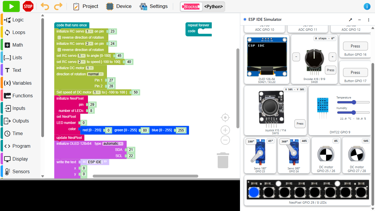
The program remains running in an empty loop. You can browse the panel and watch the outputs; you end it with the button Stop program.
What happens after restart
Run code will start the program from the beginning. Program variables are not carried over from the previous run, but some controls in the open panel retain their position.
| Driver or value | On a normal stop and restart |
|---|---|
| ADC sliders, Temperature and Humidity | They will leave the last set values in the open panel. A new run can read them right away. |
| Joystick a jeho stisk | It will return to the center and relaxed state. |
| Buttons | The inputs are set to the released state. |
| Encoder | The model in the panel starts from zero; the example also recreates its program counter. |
| Variables and measured values in the program | It will be created again during initialization and further measurements. |
That's why the repeatedly run example can immediately display, for example, the temperature 80 °C, if you previously set it with the slider. Default 22 °C is not fixed in the program.
Refreshing the entire page or recreating the panel will return its drivers to their default settings. The shared project saves the blocks and CPU selection, not the manually set slider positions. The files saved in the simulator are a separate thing; their preservation is explained by simulator overview.
Tips and pitfalls
- The component does not respond: compare the program pins with the table and after changing the blocks, run the program again.
- Reading keeps returning old data: for DHT check new measurement; for other inputs, verify that you read them repeatedly, and not just once at startup.
- OLED or NeoPixel not showing change: check redraw or update command.
- Another instance is controlled: for servo, motor, joystick and encoder, the number in the control block must match the initialization.
- The block is in the menu, but you can't find the component in the panel: the presence of the block itself does not mean that the simulator models the corresponding device. For example, the HC-SR04 does not have its own virtual component in this panel. For the first attempts, choose from the overview above.